- 您现在的位置:买卖IC网 > Sheet目录219 > D3SH-B1R1 (Omron Electronics Inc-EMC Div)SWITCH LEVER RIGHT SPST-NC SMD
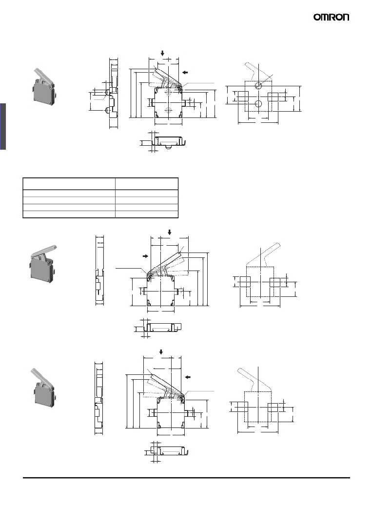
Note: 1. Unless otherwise specified, all units are in millimeters and a tolerance of ± 0.15 mm applies to all dimensions
2. The operating characteristics are for operation in the A direction ( ↓ ) and B direction ( → , ← ).
Left operating – with Boss
A
D3SH- @ 1L
(0.9)
0.6 8
(2.2)
R0.2
2.3
1.1
B
2- φ 0.7
+0.05
0
0.4
φ 0.6 ± 0.05
center of rotation
2 ± 0.1
C0.15
0. 8
0.25
0.4 2. 8 ± 0.07
3.1
2 ± 0.05 1.1
0.4
0.55
1.65
2. 8
1.65
2.2
3
4.4
0.9 ± 0.05
0.39
PCB mountin g hole and land dimensions (Reference)
( V ie w from s w itch top)
0.5
0.36
■ Long Lever Models
Model
Operating force (OF) max.
Free position (FP)
Operating position (OP)
Total travel position (TTP)
D3SH- @@ R1
D3SH- @@ L1
24 gf
5.9 ± 0.3 mm
5.4 ± 0.3 mm
3.8 ± 0.2 mm
Right operating – without Boss
A
D3SH- @ 0R1
(0.9)
0.6 8
1.1
3
(3.1)
R0.2
B
center of rotation
0.25
1.1
0.4
0.55
3.1 0. 8
0.4
1.65
0.9 ± 0.05
0.39
3
1.65
2.2
4.4
PCB mountin g land Dimension (Reference)
( V ie w from s w itch top)
0.5
0.36
Left operating – without Boss
A
D3SH- @ 0L1
(0.9)
0.6 8
R0.2
(3.1)
3
1.1
B
center of rotation
0.25
1.1
0.4
0.55
0. 8
0.4
3.1
1.65
1.65
2.2
0.9 ± 0.05
0.39
3
4.4
PCB mountin g land Dimension (Reference)
( V ie w from s w itch top)
0.5
0.36
66
Surface Mount Detection Switch
D3SH
发布紧急采购,3分钟左右您将得到回复。
相关PDF资料
D3SK-B1R
SWITCH DETECT SPST-NC RIGHT SMD
D3V-165-1C5
SWITCH LEVER SPDT 16A .250 QC
D3V-6G26-2C3-T
SWITCH LEVER 6A SPDST-NC .250QC
D44L-R1ML
SWITCH LEVER SPDT 10A QC TERM
D5F-H004
SWITCH HIGH PRECISION LIMIT
D5V0L1B2LP-7B
TVS DIODE 5V 1CH BI DFN1006-2
D5V0L1B2LP4-7B
TVS DIODE 5V 1CH BI DFN1006-2
D5V0L1B2T-7
TVS DIODE 5V 1CH BI SOD523
相关代理商/技术参数
D3SK
制造商:OMRON 制造商全称:Omron Electronics LLC 功能描述:Surface Mount Detection Switch
D3SKA0L
制造商:Omron Electronic Components LLC 功能描述:DETECTION SWITCH - Tape and Reel 制造商:Omron Electronic Components LLC 功能描述:SWITCH DETECT SPST-NO LEFT SMD
D3SK-A0L
功能描述:检测开关 SPST-NO, Left W/O Boss
RoHS:否 制造商:ALPS 操作方向:Lengthwise / Across / Diagonally 触点额定值:1 mA at 5 V 工作力:0.35 N 启动行程:3.46 mm 端接类型:PCB 主体大小:3.8 mm L x 3.6 mm W x 1 mm H 封装:Reel
D3SKA0L6
制造商:Omron Electronic Components LLC 功能描述:DETECTION SWITCH - Tape and Reel 制造商:Omron Electronic Components LLC 功能描述:SWITCH DETECT SPST-NO LEFT SMD
D3SK-A0L-6
功能描述:检测开关 SPST-NO, Left W/O Boss
RoHS:否 制造商:ALPS 操作方向:Lengthwise / Across / Diagonally 触点额定值:1 mA at 5 V 工作力:0.35 N 启动行程:3.46 mm 端接类型:PCB 主体大小:3.8 mm L x 3.6 mm W x 1 mm H 封装:Reel
D3SKA0R
制造商:Omron Electronic Components LLC 功能描述:DETECTION SWITCH - Tape and Reel 制造商:Omron Electronic Components LLC 功能描述:SWITCH DETECT SPST-NO RIGHT SMD
D3SK-A0R
功能描述:检测开关 SPST-NO, Right W/O Boss
RoHS:否 制造商:ALPS 操作方向:Lengthwise / Across / Diagonally 触点额定值:1 mA at 5 V 工作力:0.35 N 启动行程:3.46 mm 端接类型:PCB 主体大小:3.8 mm L x 3.6 mm W x 1 mm H 封装:Reel
D3SKA0R6
制造商:Omron Electronic Components LLC 功能描述:DETECTION SWITCH - Tape and Reel 制造商:Omron Electronic Components LLC 功能描述:SWITCH DETECT SPST-NO RIGHT SMD
